When it comes to accurate and repeatable flow measurement in demanding industries, turbine flow meters have stood the test of time. Known for their high precision and robust construction, these meters are trusted in everything from aerospace fuel systems to cryogenic liquid transfer. But what exactly makes them work, and why do engineers continue to rely on them despite the growing variety of flow measurement technologies? In this article, we will explore the engineering principles, core components, and operating process of turbine flow meters, as well as the advantages, limitations, and real-world applications that define their place in modern industry.
The Basics of Flow Measurement
At its core, flow measurement is about determining how much fluid is moving through a system. That measurement can be expressed in terms of volume or mass. In industrial instrumentation, devices generally fall into two categories.
Volumetric flow meters measure the amount of space that a fluid occupies in a given time frame. Common engineering units for this type of measurement include gallons per minute, liters per second, or cubic meters per hour. Mass flow meters, on the other hand, measure the weight of the fluid moving through the pipe, often in kilograms per hour or pounds per minute.
Turbine flow meters belong to the volumetric category. They measure fluid velocity and convert it into a volumetric flow rate, which can then be integrated over time to determine the total volume. This makes them an excellent choice in situations where the density of the fluid is stable and accuracy in volumetric terms is the priority.
Core Components of a Turbine Flow Meter
The performance of a turbine flow meter is determined by the precision and quality of its components. Each part is engineered for a specific function and is designed to withstand the mechanical and environmental stresses of its intended application.
The housing, sometimes referred to as the body of the meter, is typically made from stainless steel, aluminum, or specialty alloys. It provides the structural framework for the meter and protects the sensitive internal parts while also containing and directing the fluid.
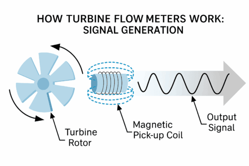
The rotor or turbine blades form the heart of the device. These blades are shaped and angled to optimize sensitivity to fluid velocity while minimizing drag. The geometry of the blades directly influences the meter’s accuracy and its ability to respond quickly to changes in flow.
Bearings support the rotor’s rotation. Depending on the flow rates, viscosities, and temperatures involved, the meter might use ball bearings, jewel bearings, or hydrodynamic designs. The choice of bearing impacts not only the accuracy of the measurement but also the durability of the meter.
The pickup sensor is another critical component. This device detects the passing of the rotor blades and generates an electrical pulse signal. Many turbine meters use magnetic or modulated carrier sensors that respond to the motion of the rotor without direct contact.
Finally, flow straighteners are often installed upstream of the rotor. These vanes or grids help to align the fluid stream and reduce turbulence, ensuring that the flow enters the rotor in a consistent and predictable manner.
How It Works: Step-by-Step
When fluid enters a turbine flow meter, it first passes through the upstream support which conditions the flow and reduces unwanted swirl. This step is important because an uneven flow profile can cause the rotor to spin irregularly, leading to inaccurate readings.
As the fluid moves into the rotor section, it strikes the blades and causes them to spin. The speed of rotation is directly proportional to the velocity of the fluid moving through the meter.
Every time a blade passes the pickup sensor, the sensor detects its movement and produces an electrical pulse. The number of pulses recorded over a specific period is directly related to the volumetric flow rate. By integrating these readings over time, the total volume of fluid that has passed through the meter can be calculated.
This operating principle is elegantly simple. Faster flow results in faster rotor rotation, which generates more pulses per second. Slower flow produces fewer pulses. This direct relationship between flow velocity and rotor speed is what allows turbine flow meters to be highly accurate once properly calibrated.
The Engineering Behind the Accuracy
Turbine flow meters are valued for their ability to deliver precise measurements, often within plus or minus 1.00 percent to 0.5 percent of the reading. Achieving this level of accuracy depends on both careful calibration and consistent fluid dynamics.
The proportionality between rotor speed and fluid velocity allows for calibration curves that are straightforward and reliable. Many meters are calibrated against standards traceable to the National Institute of Standards and Technology (NIST), ensuring consistent performance across operating conditions.
However, the properties of the fluid can influence the measurement. Viscosity, density, and temperature changes can affect how the rotor spins and how the sensor detects its movement. Turbine flow meters are often tailored or calibrated for the specific fluid they will measure to account for these factors.
Flow conditions also matter. A concept known as the Reynolds number helps determine whether the flow is in a range where the turbine can perform accurately. At very low flow rates, the rotor may not spin as steadily, reducing accuracy.
Advantages of Turbine Flow Meters
One of the main reasons turbine flow meters are still widely used is their high accuracy. They are well suited to applications where even small measurement errors can have significant financial or operational impacts.
They also have a wide flow range, meaning they can maintain accuracy across varying operating conditions. Their mechanical simplicity and proven track record give them an edge in industries that demand reliability. Additionally, they are versatile enough to measure liquids, gases, and cryogenic fluids with proper design considerations.
Limitations and Engineering Challenges
Turbine flow meters are not without their challenges. Changes in fluid viscosity can alter how the rotor behaves, which in turn affects accuracy. Bearings are subject to wear, especially when exposed to abrasive or contaminated fluids, and may require periodic replacement.
The cleanliness of the fluid is another factor. Solids, debris, or buildup inside the meter can cause drag on the rotor or damage to components. Installation conditions, such as insufficient straight-run piping upstream and downstream, can also introduce turbulence and measurement errors.
Real-World Applications
Turbine flow meters are used extensively in hydrogen measurement, both in gaseous and liquid states, where accuracy and reliability are critical. In cryogenic applications, such as the measurement of LNG, they are engineered to operate in extremely low temperatures with specialized materials and bearing designs.
In aerospace, turbine flow meters are used in fuel systems where precise monitoring of fuel consumption is essential for performance, safety, and compliance. In the pharmaceutical industry, they provide accurate batching and ingredient measurement that supports strict quality control standards.
Maintenance and Longevity
To keep a turbine flow meter performing at its best, proper maintenance is essential. Using filtration to keep debris out of the meter will help prevent premature wear on the rotor and bearings. Regular calibration checks are necessary to maintain accuracy, especially in high-stakes applications like custody transfer. Bearings should be inspected and replaced when worn, and operating conditions should be reviewed to ensure the meter is not exposed to extreme factors beyond its design limits.
Conclusion
The engineering behind turbine flow meters combines precision machining, fluid dynamics, and durable materials to deliver reliable, accurate measurements. By understanding how they work and the conditions they require to operate at peak performance, engineers and operators can make better choices in selecting, installing, and maintaining these meters. Whether for hydrogen fueling, aerospace fuel monitoring, or cryogenic liquid transfer, turbine flow meters remain a dependable solution for high-accuracy flow measurement.