Selecting the correct output signal is just as important as choosing the right flow meter. While engineers often focus on accuracy, flow range, pressure rating, and materials of construction, the output signal ultimately determines how flow data is transmitted, monitored, and used throughout a facility. Two of the most common signal types found on turbine flow meters and other industrial flow measurement devices are pulse outputs and 4-20mA analog outputs.
Both signal types have been widely used across industries such as manufacturing, chemical processing, oil and gas, power generation, water treatment, and food processing. However, they serve different purposes. A pulse output excels at measuring total volume, while a 4-20mA signal is often preferred for real-time process monitoring and control. Understanding how each signal works and where it performs best can help engineers select the most effective solution for their application.
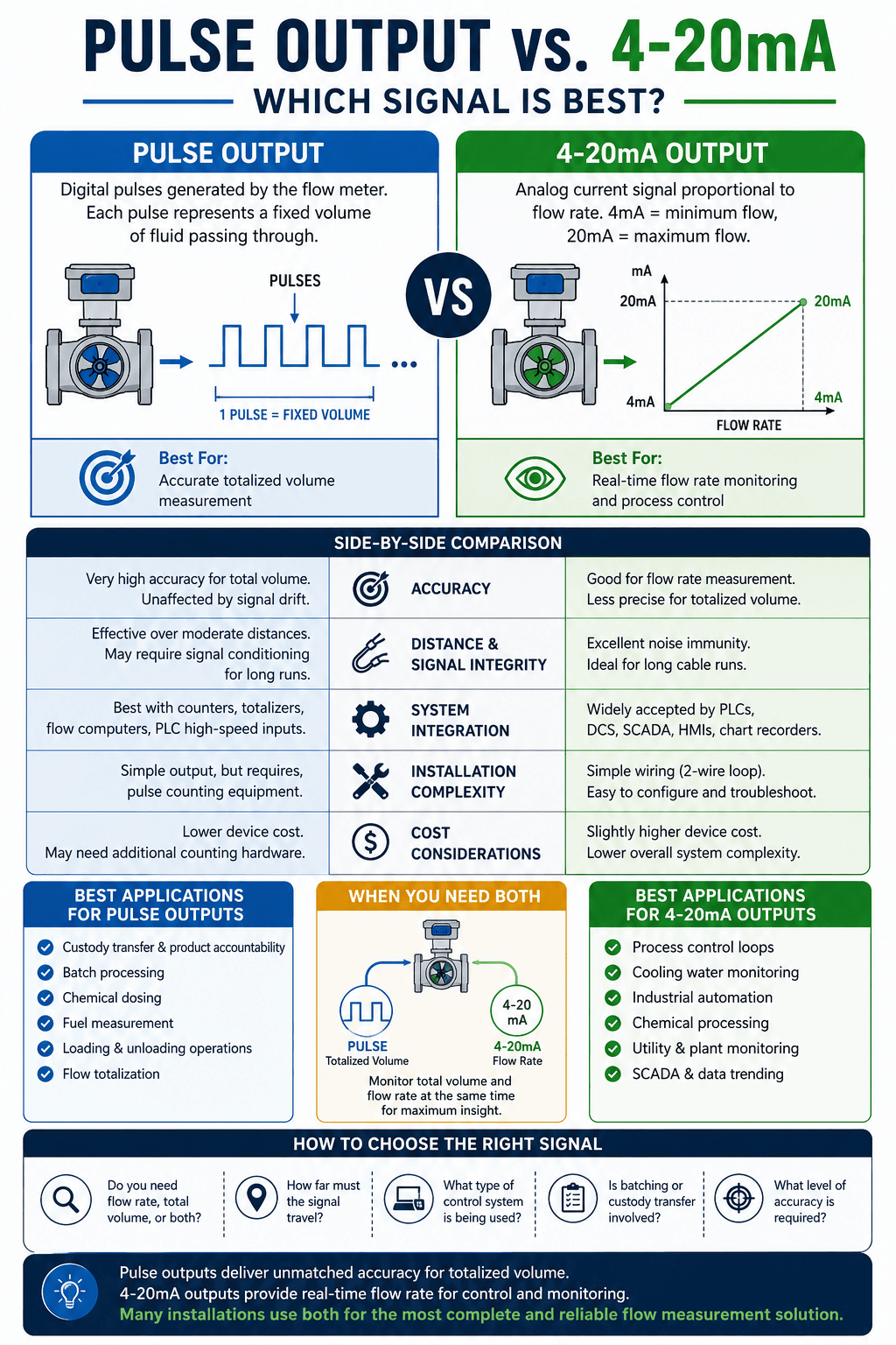
Understanding Pulse Outputs
A pulse output generates a series of electrical pulses that correspond directly to the volume of fluid passing through a flow meter. In turbine flow meters, the rotating rotor produces pulses as fluid flows through the meter. Each pulse represents a specific quantity of fluid, which is defined by the meter’s K-Factor. By counting pulses over time, a control system can accurately calculate total flow volume.
Because pulse outputs are based on discrete counts rather than analog values, they are exceptionally accurate for totalization applications. Every pulse represents a measurable increment of fluid, making pulse signals a preferred choice for custody transfer, batching, blending, loading operations, and chemical dosing systems.
One of the greatest advantages of pulse outputs is their ability to maintain accuracy without signal drift. Since the receiving device simply counts pulses, there is little opportunity for gradual degradation in measurement accuracy due to electrical noise or component aging. Pulse outputs are also highly compatible with flow computers, totalizers, counters, and PLC high-speed input modules.
Despite their advantages, pulse outputs are not always the ideal solution. To interpret a pulse signal, the receiving device must count and process pulses. At very high flow rates, pulse frequencies can become extremely high, requiring specialized electronics capable of handling fast pulse trains. Additionally, pulse outputs are generally better suited for measuring accumulated volume than for providing a smooth, real-time indication of instantaneous flow rate.
Understanding 4-20mA Outputs
The 4-20mA signal has long been considered the industry standard for transmitting process variables throughout industrial facilities. Rather than generating pulses, the flow meter converts flow rate into a proportional current signal. Typically, 4mA represents the minimum flow rate in a configured range, while 20mA represents the maximum flow rate.
For example, a flow meter scaled from 0 to 100 gallons per minute would transmit 4mA at zero flow and 20mA at 100 GPM. A reading of 12mA would represent approximately 50 GPM. This continuous signal allows operators and control systems to monitor flow rate in real time.
One reason 4-20mA outputs remain so popular is their ability to transmit signals over long distances with excellent resistance to electrical interference. Current loops are inherently less susceptible to voltage drops and noise than many other signal types, making them ideal for large industrial facilities where sensors may be located hundreds or even thousands of feet from control rooms.
The analog signal is also easily integrated into PLCs, DCS platforms, SCADA systems, chart recorders, and virtually every modern industrial control system. Process engineers often rely on 4-20mA outputs when flow data is needed for control loops, alarming, trending, or process optimization.
While highly effective for flow rate monitoring, analog signals are not always the best choice for totalized volume measurement. Since the signal represents a continuously changing value rather than individual flow increments, totalization calculations depend on sampling rates and system resolution. Although modern control systems perform these calculations effectively, pulse outputs generally provide superior precision when measuring accumulated volume.
Pulse Output vs. 4-20mA: Key Differences
When comparing the two signal types, the most important consideration is the measurement objective. Pulse outputs are designed to provide highly accurate volume measurement, while 4-20mA outputs are optimized for transmitting real-time flow rate information.
Pulse outputs are commonly selected for:
- Custody transfer and product accountability
- Batch processing operations
- Chemical dosing systems
- Fuel transfer applications
- Loading and unloading systems
- Flow totalization requirements
Meanwhile, 4-20mA outputs are frequently used for:
- Process control loops
- Cooling water monitoring
- Industrial automation systems
- Utility monitoring
- SCADA integration
- Continuous process optimization
Signal transmission distance is another factor. While pulse signals can travel considerable distances when properly conditioned, 4-20mA current loops are generally preferred for long cable runs because of their excellent immunity to electrical noise and voltage losses.
Integration requirements also influence the decision. If the goal is to drive a control valve, maintain a target flow rate, or display a live process value on an HMI, a 4-20mA signal is often the simplest and most effective solution. If the objective is to track exactly how much fluid has been delivered, transferred, or consumed, pulse outputs typically provide superior results.
When Using Both Signals Makes Sense
Many modern flow meter installations use both pulse and 4-20mA outputs simultaneously. This approach allows operators to benefit from the strengths of each signal type without compromise.
For example, a chemical injection skid may use the pulse output to accurately track chemical consumption while using the 4-20mA output to continuously monitor injection rates. Similarly, a fuel transfer system may use pulse signals for custody transfer calculations while transmitting a 4-20mA signal to the plant control system for operational monitoring.
Dual-output configurations are common in turbine flow meter installations because they provide greater flexibility for future expansion and integration. Rather than choosing between volume measurement and flow rate monitoring, facilities can obtain both types of data from a single flow meter.
Which I/O Is Best?
Pulse outputs and 4-20mA outputs each serve an important role in industrial flow measurement. Pulse signals excel in applications where precise totalized volume measurement is critical, while 4-20mA signals remain the preferred choice for real-time flow monitoring and process control. The best option depends on how the flow data will be used within the facility.
For many applications, the ideal solution is not choosing one signal over the other but utilizing both. By combining the volume accuracy of pulse outputs with the process control capabilities of 4-20mA signals, engineers can maximize the value of their flow measurement system and ensure reliable performance across a wide range of operating conditions.